17
LTC3445
3445fa
APPLICATIO S I FOR ATIO
U
U
U
BUCK REGULATOR
The basic LTC3445 application circuit is shown on the first
page of this data sheet. External component selection is
driven by the load requirement and begins with the selec-
tion of L followed by C
IN
and C
OUT
.
Inductor Selection
For most applications, the value of the inductor will fall in
the range of 1礖 to 4.7礖. Its value is chosen based on the
desired ripple current. Large value inductors lower ripple
current and small value inductors result in higher ripple
currents. Higher V
CC1
or lower V
OUT
also increases the
ripple current as shown in Equation 1. A reasonable
starting point for setting ripple current is I
L
= 240mA
(40% of 600mA).
=
( )()
?/DIV>
?/DIV>
?/DIV>
?/DIV>
?/DIV>
?/DIV>
I
f L
V
V
V
L
OUT
OUT
CC
1
1
1
(1)
The DC current rating of the inductor should be at least
equal to the maximum load current plus half the ripple
current to prevent core saturation. Thus, a 720mA rated
inductor should be enough for most applications (600mA
+ 120mA). For better efficiency, choose a low DC-resis-
tance inductor.
The inductor value also has an effect on Burst Mode
operation. The transition to low current operation begins
when the inductor current peaks fall to approximately
200mA. Lower inductor values (higher I
L
) will cause this
to occur at lower load currents, which can cause a dip in
efficiency in the upper range of low current operation. In
Burst Mode operation, lower inductance values will cause
the burst frequency to increase.
Inductor Core Selection
Different core materials and shapes will change the size/
current and price/current relationship of an inductor.
Toroid or shielded pot cores in ferrite or permalloy mate-
rials are small and dont radiate much energy, but gener-
ally cost more than powdered iron core inductors with
similar electrical characteristics. The choice of which style
inductor to use often depends more on the price vs size
requirements and any radiated field/EMI requirements
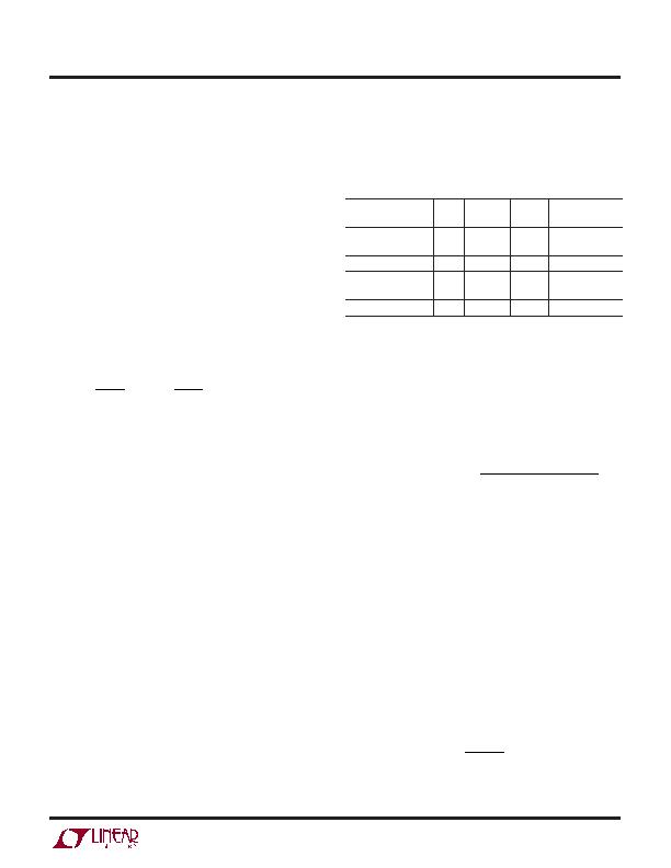
than on what the LTC3445 requires to operate. Table 1
shows some typical surface mount inductors that work
well in LTC3445 applications.
Table 1
MANUFACTURER VALUE DCR MAX DC SIZE
PART NUMBER
(?/SPAN>H) (m& MAX) (A) L ?/SPAN> W ?/SPAN> H (mm
3
)
Sumida CDRH3D16/ 2.2 72 1.2 4.0 ?4.0 ?1.8
HP2R2
Sumida CR434R7 4.7 109 1.15 4.0 ?4.5 ?3.5
TDK TDK7030T-
2.2 12 5.5 7.3 ?6.8 ?3.2
2R2M5R4
Coilcraft D03316P-222 2.2 12
7 12.45 ?9.4 ?5.21
C
IN
and C
OUT
Selection
In continuous mode, the source current of the top MOSFET
is a square wave of duty cycle V
OUT
/V
CC1
. To prevent large
voltage transients, a low ESR input capacitor sized for the
maximum RMS current must be used. The maximum
RMS capacitor current is given by:
C
I
V V V
V
IN
OMAX
OUT CC OUT
CC
required I
RMS
E
( )
[
]
1
12
1
/
(2)
This formula has a maximum at V
CC1
= 2V
OUT
, where I
RMS
= I
OUT
/2. This simple worst-case condition is commonly
used for design because even significant deviations do not
offer much relief. Note that the capacitor manufacturers
ripple current ratings are often based on 2000 hours of life.
This makes it advisable to further derate the capacitor, or
choose a capacitor rated at a higher temperature than
required. Always consult the manufacturer if there is any
question.
The selection of C
OUT
is driven by the required effective
series resistance (ESR). Typically, once the ESR require-
ment for C
OUT
has been met, the RMS current rating
generally far exceeds the I
RIPPLE(P-P)
requirement. The
output ripple V
OUT
is determined by:
E +
?/DIV>
?/DIV>
?/DIV>
?/DIV>
?/DIV>
?/DIV>
V I ESR
fC
OUT L
OUT
1
8
(3)
发布紧急采购,3分钟左右您将得到回复。
相关PDF资料
LTC3446IDE#PBF
IC REG TRPL BCK/LINEAR 14-DFN
LTC3537EUD#TRPBF
IC REG DL BST/LINEAR SYNC 16-QFN
LTC3541EDD#TRPBF
IC REG DL BCK/LINEAR SYNC 10-DFN
LTC3670EDDB#TRPBF
IC REG TRPL BCK/LINEAR 12DFN
LTC3672BEDC-1#TRPBF
IC REG TRPL BCK/LINEAR 8-DFN
LTC3700EMS#TRPBF
IC REG DL BUCK/LINEAR 10MSOP
LTC4151HMS#TRPBF
IC PWR MONITOR MS 80V SD 10MSOP
LTC4210-2CS6#TRM
IC CONTROLLER HOT SWAP TSOT23-6
相关代理商/技术参数
LTC3446
制造商:LINER 制造商全称:Linear Technology 功能描述:Monolithic Buck Regulator with Dual VLDO Regulators
LTC3446EDE
制造商:LINER 制造商全称:Linear Technology 功能描述:Monolithic Buck Regulator with Dual VLDO Regulators
LTC3446EDE#PBF
功能描述:IC REG TRPL BCK/LINEAR 14-DFN RoHS:是 类别:集成电路 (IC) >> PMIC - 稳压器 - 线性 + 切换式 系列:- 标准包装:2,500 系列:- 拓扑:降压(降压)同步(3),线性(LDO)(2) 功能:任何功能 输出数:5 频率 - 开关:300kHz 电压/电流 - 输出 1:控制器 电压/电流 - 输出 2:控制器 电压/电流 - 输出 3:控制器 带 LED 驱动器:无 带监控器:无 带序列发生器:是 电源电压:5.6 V ~ 24 V 工作温度:-40°C ~ 85°C 安装类型:* 封装/外壳:* 供应商设备封装:* 包装:*
LTC3446EDE#TRPBF
功能描述:IC REG TRPL BCK/LINEAR 14-DFN RoHS:是 类别:集成电路 (IC) >> PMIC - 稳压器 - 线性 + 切换式 系列:- 标准包装:2,500 系列:- 拓扑:降压(降压)同步(3),线性(LDO)(2) 功能:任何功能 输出数:5 频率 - 开关:300kHz 电压/电流 - 输出 1:控制器 电压/电流 - 输出 2:控制器 电压/电流 - 输出 3:控制器 带 LED 驱动器:无 带监控器:无 带序列发生器:是 电源电压:5.6 V ~ 24 V 工作温度:-40°C ~ 85°C 安装类型:* 封装/外壳:* 供应商设备封装:* 包装:*
LTC3446EDE-PBF
制造商:LINER 制造商全称:Linear Technology 功能描述:Monolithic Buck Regulator with Dual VLDO Regulators
LTC3446EDE-TRPBF
制造商:LINER 制造商全称:Linear Technology 功能描述:Monolithic Buck Regulator with Dual VLDO Regulators
LTC3446IDE
制造商:LINER 制造商全称:Linear Technology 功能描述:Monolithic Buck Regulator with Dual VLDO Regulators
LTC3446IDE#PBF
功能描述:IC REG TRPL BCK/LINEAR 14-DFN RoHS:是 类别:集成电路 (IC) >> PMIC - 稳压器 - 线性 + 切换式 系列:- 标准包装:2,500 系列:- 拓扑:降压(降压)同步(3),线性(LDO)(2) 功能:任何功能 输出数:5 频率 - 开关:300kHz 电压/电流 - 输出 1:控制器 电压/电流 - 输出 2:控制器 电压/电流 - 输出 3:控制器 带 LED 驱动器:无 带监控器:无 带序列发生器:是 电源电压:5.6 V ~ 24 V 工作温度:-40°C ~ 85°C 安装类型:* 封装/外壳:* 供应商设备封装:* 包装:*